
Software Architecture · Editable reference architecture
Service oriented architecture
An editable service oriented architecture reference showing Business client → Service contract → Integration bus and downstream dependencies. Shared integration must not hide service ownership.
Open & Edit in DrawArc (Free, No Login Required)Your changes stay in a separate draft on this browser. Download an editable project to keep a portable copy.
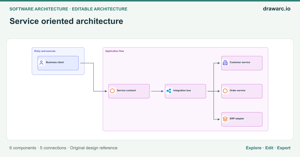
6 components · 5 connections · Open the editor to zoom, move nodes and edit source.
Architectural overview
Service oriented architecture addresses the responsibilities and boundaries shown in this reference rather than prescribing an entire production deployment. The primary flow starts at Business client and reaches Customer service through Service contract, Integration bus. Use this view to explain which component initiates work, which component owns a decision, and where a dependency can affect the caller. Shared integration must not hide service ownership.
The diagram contains 6 distinct components and 5 directed relationships. A separate path connects Integration bus → Order service. A separate path connects Integration bus → ERP adapter. These arrows describe logical interactions; they do not establish authentication, network access, atomic transactions or delivery guarantees. Label the actual protocol, payload contract and owner when adapting the drawing to your system. Keep synchronous and asynchronous boundaries explicit so that a reviewer can identify where a request ends and a later operation begins.
Before implementing this architecture, define expected load, data classification, latency budgets and recovery objectives. Give Service contract a bounded dependency timeout and a documented failure response. Assign ownership to any state or external service added during implementation. Validate the decision above against your workload instead of treating the presence of a component as proof of reliability. Open the editable canvas, replace generic labels with real deployment units, and document the decisions that differ from this reference.
The real-world problem
Design or explain service oriented architecture with explicit ownership and dependency paths. Shared integration must not hide service ownership.
Data flow
Connections from this diagram. Branches and control signals are not a single chronological sequence.
- Business client → Service contract. Define the interaction contract and trace the resulting response or state change.
- Service contract → Integration bus. Define the interaction contract and trace the resulting response or state change.
- Integration bus → Customer service. Define the interaction contract and trace the resulting response or state change.
- Integration bus → Order service. Define the interaction contract and trace the resulting response or state change.
- Integration bus → ERP adapter. Define the interaction contract and trace the resulting response or state change.
Security boundaries
- Authenticate callers at the boundary before Service contract accepts protected work; authorize the specific operation rather than trusting network placement.
- Use separate service identities and least-privilege permissions for Service contract, Integration bus, Customer service. Encrypt sensitive traffic, protect credentials and avoid placing confidential payloads in logs.
- Validate untrusted inputs and restrict administrative/configuration endpoints separately from the main flow.
Failure handling
Service contract is unavailable or slow
Response: Apply bounded timeouts and controlled backoff only where retrying is safe. Return an explicit failure or durable acceptance; do not report success before required work is committed.
Verify: Interrupt Service contract in an isolated test and measure errors, recovery and any repeated side effects.
A dependency repeats or drops a request
Response: Use operation identifiers and explicit acknowledgement/reconciliation where needed. Verify idempotency before enabling retries.
Verify: Exercise the failure path with representative records and verify both the visible response and the resulting state.
An invalid or incompatible input reaches Service contract
Response: Validate the input contract before effects are committed. Preserve rejected input identifiers without exposing secrets, and document a safe replay or correction procedure.
Verify: Send malformed and older-version inputs through Business client and verify rejection, observability and unchanged valid state.
Trade-offs and alternatives
Shared integration must not hide service ownership.
- Benefit
- Makes the ownership and interaction boundaries visible for a focused design review.
- Cost
- The 6 illustrated components still require contracts, monitoring and operational ownership; extra boundaries can add latency and failure modes.
- Alternative
- Use a simpler deployment when it meets the same requirements, or split a boundary only after measuring a specific need.
Logical boundaries versus deployment units in Service oriented architecture
- Benefit
- Keeps the responsibilities of Business client, Service contract, Integration bus visible without requiring a separate server for each box.
- Cost
- A logical view does not establish isolation, independent scaling or high availability; those require a separate deployment design and operational tests.
- Alternative
- Co-locate components in a simpler deployment first when ownership and workload requirements permit it.
When to use this architecture
- Explain service oriented architecture to engineers or stakeholders using a concrete visual flow.
- Review this decision before deployment: Shared integration must not hide service ownership.
- Adapt a starting diagram for your own requirements, then record and validate every changed boundary.
Key components
- Business client
- Business client participates in service oriented architecture. Business client → Service contract. Define its contract, owner and access permissions in your implementation.
- Service contract
- Service contract participates in service oriented architecture. Business client → Service contract; Service contract → Integration bus. Define its contract, owner and access permissions in your implementation.
- Integration bus
- Integration bus participates in service oriented architecture. Service contract → Integration bus; Integration bus → Customer service; Integration bus → Order service; Integration bus → ERP adapter. Define its contract, owner and access permissions in your implementation.
- Customer service
- Customer service participates in service oriented architecture. Integration bus → Customer service. Define its contract, owner and access permissions in your implementation.
- Order service
- Order service participates in service oriented architecture. Integration bus → Order service. Define its contract, owner and access permissions in your implementation.
- ERP adapter
- ERP adapter participates in service oriented architecture. Integration bus → ERP adapter. Define its contract, owner and access permissions in your implementation.
Questions about this template
What does this service oriented architecture diagram show?
It shows 6 components with the core flow Business client → Service contract → Integration bus → Customer service. Shared integration must not hide service ownership.
Can I edit this diagram without signing in?
Yes. Open the template in the browser-local canvas to change nodes, connections and source. AI generation and cloud account storage require sign-in.
Is this a complete production implementation?
No. It is an editable reference. Validate the security controls, dependency behavior, capacity and recovery plan against your own requirements before implementation.
Validate your implementation
Use the relevant platform documentation to verify service limits, supported features and configuration. This diagram is an original reference rather than a reproduction of a provider deployment.